index_45
UNCLASSIFIED
Implementing Security on Cisco Routers
Version 1.0g
UNCLASSIFIED
45
4. Implementing Security on Cisco
Routers
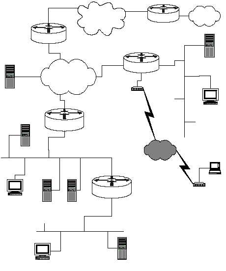
The diagram below shows a simple network configuration. The structures and
addresses illustrated here are used for all of the examples in Sections 4, 5, and 6.
Figure 4-1 is simply a vehicle for presenting security guidance about routers, it is not
a design for a secure network. However, this architecture accurately reflects the
kinds of networks found in many organizations.
Central
LAN 2
14.2.9.0/24
Facility Network
14.1.0.0/16
User Host
14.2.9.6/24
Admin Server
14.2.9.1/24
14.2.9.250/24
14.1.15.250/16
Internet
North
(Perimeter router)
14.1.1.250/16
DNS
Server
14.1.1.2/16
Public Web Server
14.2.9.2/24
South (firewall)
Protected Enclave
14.2.10.0/24
14.2.9.64/24
14.2.10.64/24
User Host
14.2.10.6/24
FTP & Web Server
14.2.10.2/24
East
LAN 1
14.2.6.0/24
14.1.1.20/16
14.2.6.250/24
User Host
14.2.6.6/24
Remote Host
modem
Telephone
Network
modem
Authentication
Server
14.2.6.18/24
Remote
Remote Network
7.0.0.0/8
7.12.1.20
14.2.0.20
Mail Server
14.2.9.3/24
net
access
eth 0
eth 1
eth 0/0
eth 0/1
eth 0/0
eth 0/1
Figure 4-1: Network Diagram for Examples